Charging batteries is simple (in theory) – put a voltage across the terminals and the battery charges. If safe charging, fast charging and/or maximum battery life are important, that’s when things get complicated. This article will consider various aspects of charging nickel-metal-hydride (NiMH), nickel cadmium (NiCd), lithium-ion (Li-ion), and lead acid (PbA) batteries.
The three most common batteries found in electronic devices are NiMH, NiCd, and Li-ion. For those batteries, the C rate is an important consideration when defining charging parameters. “C” refers to the battery’s capacity when discharged over a one-hour period. For example, a battery rated for 1,000mAh capacity could be charged at 0.33C, resulting in a charge current of about 0.33mA over three hours to reach full charge. The capacity of these batteries is determined relative to the minimum allowable voltage, called the cut-off voltage. It is this voltage that generally defines the “empty” state of the battery. At that point, there is still charge left, but drawing it out risks damaging the battery.
For PbA batteries, the ampere-hour (Ah) rating is usually an important consideration when defining a charging methodology. The Ah rating of the battery is calculated based on a full discharge; no cutoff voltage is considered and is not necessarily the actual useable capacity.
Charging batteries in electronic devices
The nominal voltage of NiMH and NiCd batteries is about 1.2 V/cell, and they usually should be charged up to 1.5V to 1.6 V per cell. Delta temperature (dT/dt), temperature threshold, peak voltage detection, negative delta voltage, and simple timers are among the methods used to determine when to stop charging NiMH and NiCd batteries. For more critical applications, one or more can be combined in a single charger.
Peak voltage detection is used in the constant current regulator (CCR) battery charging circuit shown below. Using a peak voltage detection point of 1.5 V/cell will result in charging to about 97% of full capacity for NiMH and NiCd batteries.
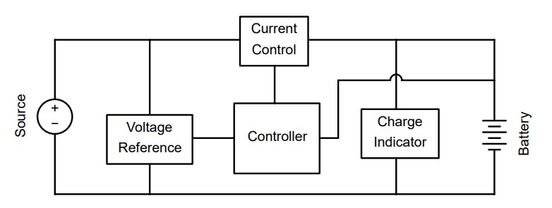
Block diagram of simple constant current regulator battery charging circuit. (Image: ON Semiconductor)
General Li-ion charging considerations
With appropriate caution, the CCR battery charger shown above could be used to charge a Li-ion battery. Li-ion batteries are often charged to 4.2 V/cell at 0.5C or less to near 1C capacity, sometimes followed by a slower charging rate. The challenge is to keep the temperature rise to under 5°C. A higher temperature during charging could lead to a catastrophic event such as fire. And the temperature of a Li-ion battery typically rises the most during the final stages of charging. This CCR controller attempts to eliminate that potential problem by not including a second, lower-rate charge stage. Eliminating the second charge stage helps to lengthen battery life in addition to helping to keep the battery operating safely. However, eliminating the second charging stage also means that the battery will only charge up to about 0.85C, or 85% of its maximum capacity.
Unless a Li-ion battery is charged very slowly (usually 0.15 C or even less), terminating the charge based on reaching a voltage of 4.2 V/cell will only charge the battery to a maximum of 0.7C. Some batteries may only reach 0.4C.
Charging Li batteries at less than 4.2 V/cell is possible but also not recommended. While other battery chemistries do not charge at low voltages, Li batteries will charge but will not reach full charge. An advantage of charging at lower voltages is that cycle life goes up substantially but with much lower capacity.
While simple constant current battery charging circuits can provide low cost and relatively slow charging, multi-stage technologies are needed for better performance. For Li-ion batteries, the charging must be terminated; trickle charging is not acceptable. Overcharge of Li-ion batteries can damage the cell, possibly plating out lithium metal and becoming hazardous.
The diagram below illustrates a more optimal approach to charging Li batteries. If the battery is fully or nearly fully depleted, the process starts with trickle charging, followed by a slighter faster pre-charge. Once a pre-determined charge level is reached, depending on the specific battery being charged, fast charging occurs based on a constant current approach until a critical battery voltage, usually about 4.2 V/cell, is reached. That is followed by constant voltage charging to complete the process. At that point, charging is terminated, and no voltage is applied to the battery.
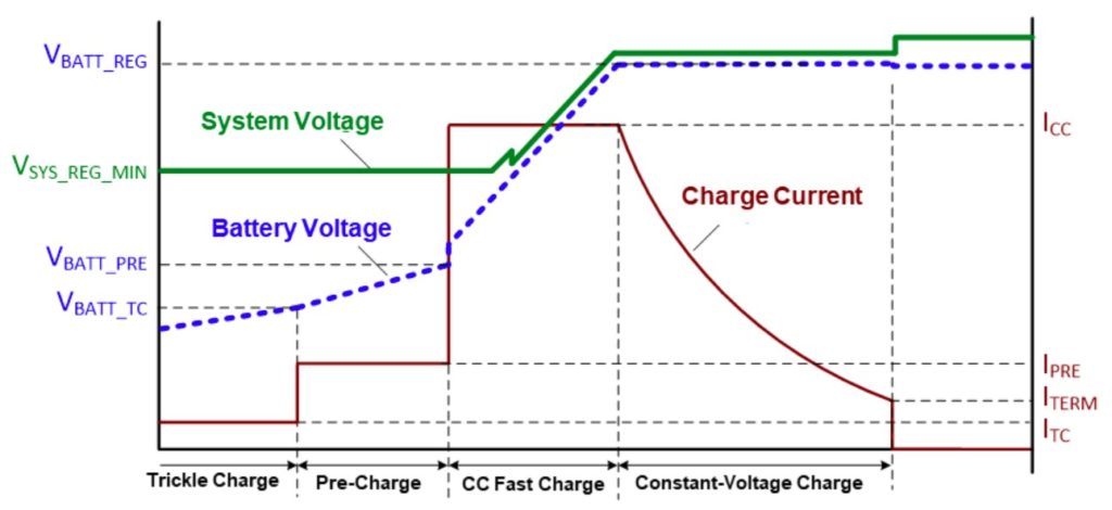
Li-ion battery charging curves. (Image: Monolithic Power Systems)
There are numerous alternative topologies for Li-ion charging. Two common ones are narrow voltage dc and hybrid power boost charging optimized for specific use cases.
Narrow voltage DC
The narrow voltage DC (NVDC) was originally an Intel™ initiative designed to increase system efficiency by lowering the voltage range of the system load in notebook and tablet computers. That is accomplished by replacing the usual battery charger with a system charger incorporating a buck converter. That enables dc/dc (buck) converter optimization and removes the power-path switch, saving dissipation, board area, and cost.
The figure below is an example of an NVDC implementation. The system is connected to the adapter through the buck converter. NVDC operates as a buck converter when the battery is being charged and when the battery supplements the adapter to provide system power.
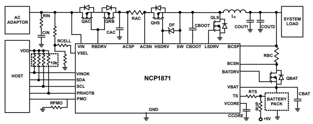
NVDC battery charger for applications such as ultra books or tablets. (Image: ON Semiconductor)
Due to the lower voltage variation, NVDC has higher overall efficiency than Hybrid Power Boost (HPB) charger (discussed in the next section), and usually offers a better line transient response. Two disadvantages of NVDC include:
- The lower system voltage results in higher bus currents which increases conduction losses in the PCB traces and negates some of the power savings achieved using lower voltage-rated devices.
- Because higher current-rated power FETs and inductors are used, the charger’s size, cost, and power dissipation may be higher.
Hybrid power boost charging
Both NVDC and HPB enable the adapter and battery to work together to supply the system load when it exceeds the adapter’s rating. HPB reverse-boosts the battery energy to the system bus. At the same time, the NVDC configuration quickly turns on QBAT (in the figure above) to enable the battery to assist the adapter and provide system power.
In an HPB configuration, the buck converter operates normally while the adapter provides system power and is charging the battery. When the adapter power is not sufficient, the buck converter runs in reverse, enabling the battery to supplement the adapter. HPB can be implemented with a conventional adapter.
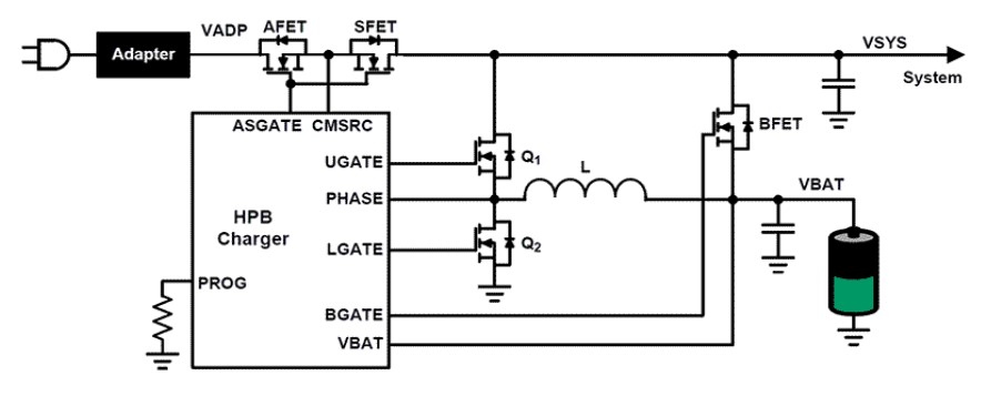
Hybrid power boost battery charger simplified schematic. (Image: Renesas)
Implementation of HPB requires changes in the battery charger controller. Compared with a conventional battery charger, HPB allows the battery to supply supplemental power when needed. The disadvantage is that the light load efficiency of the charging system is lower.
For example, in tablet and notebook computers, HPB has been used to enable both the CPU and GPU to reach their highest performance simultaneously when playing games. In this case, both the ac adapter and the battery can simultaneously supply power to the system. When the battery charge is above 40%, HPB will automatically run, depending on the program requirement. When HPB is running, the battery is discharging. When battery charge drops below 30%, HPB operation is paused, and the battery begins charging.
Three-stage charging for lead-acid
Lead acid batteries also require multiple charging stages for optimal performance. However, compared with the lithium batteries discussed above, this is a much simpler process. While PbA battery chargers are available from two to five charging stages, three-stage chargers (also called three-phase or three-step) are the most common. The three stages are; bulk, absorption, and trickle.
The DIN 41773 designation for three-phase PbA charging is “IUoU.” IUoU stands for: “I” (constant current, bulk charging), “Uo” (constant voltage, absorption charging), and “U” (also constant voltage, trickle charging). Regardless of the labels given to the three phases, the goal is to fully charge the battery in a relatively short time, maintain long battery life and keep the battery at full charge indefinitely as long as it is connected to the charger.
During the bulk stage, the battery will reach about 80% of full charge, assuming that a constant current of about 25% of the ampere-hour (Ah) rating of the battery is supplied. This 25% figure can vary from manufacturer to manufacturer, requiring the bulk charge rate to be as low as 10% of the Ah rating. In almost every case, charging faster than 25% of the Ah rating during the bulk stage will decrease battery life. A smart charger can be used to charge the battery as fast as possible while keeping the battery temperature under 100° F. While this can be effective, it may also decrease the life of some batteries, so the manufacturer’s recommendations should be followed.
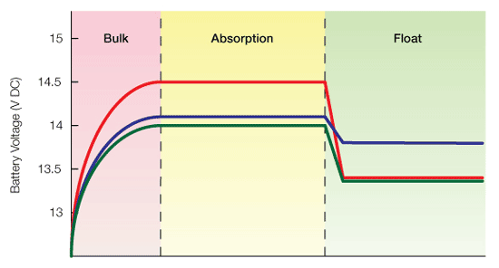
Three-stage charging scheme for sealed lead acid batteries. (Image: Vorp Energy)
During the absorption stage (sometimes called the “equalization stage”), the remaining 20% of the charging is completed. During this stage, the controller will shift to constant voltage mode, maintaining the target charging voltage, typically between 14.1Vdc and 14.8Vdc, depending on the specific type of lead-acid battery being charged, while decreasing the charging current accordingly. If a battery has been damaged (for example, by the build-up of permanent sulfation) and the current does not drop as expected, the charger should shut down or immediately switch to the float stage.
The charger reduces the charging voltage to between 13.0Vdc and 13.8Vdc, again, depending on the specific type of lead-acid battery being charged during the float stage. The charging current is reduced to more than 1% of the battery’s Ah rating. Lead-acid batteries can be kept on float indefinitely. In fact, keeping the battery on float will increase the battery’s useful life since it eliminates the possibility of self-discharge, draining the battery to unacceptably low levels and causing irreversible damage.
Summary
Battery charging is simple in theory, but practical implementations that get maximum battery performance and lifetimes are much more complex and often require multi-stage charging. While constant current regulator designs can effectively charge NiMH and NiCd batteries, they are less than effective for charging Li and PbA batteries. For Li and PbA batteries, various combinations of multi-stage constant current charging and constant voltage charging are needed to ensure maximum performance, extend battery lifetimes, and provide safe operation.
References
3 Stage Charge Controllers for Solar Battery Charging, Vorp Energy
Battery charger, Wikipedia
Constant Current Regulator Charging Circuit, ON Semiconductor
Hybrid Power Boost (HPB) Battery Charger with SMBus Interface, Renesas
How to Select a Lithium-Ion Battery Charge Management IC, Monolithic Power Systems

Hi, I was just looking at paragraph 2 and it states, “For example, a battery rated for 1,000mAh capacity could be charged at 0.33C, resulting in a charge current of about 0.33mA over three hours to reach full charge.” Should the amperage charge be 333mA (or 0.33A) over 3 hours rather than 0.33mA over 3 hours? I may be mis-understanding, so if I am, please disregard.
0,33C from 1000 mAh will result in 330mA, not 0,33 mA, as You supose.
In many off-grid installations insufficient attention is given to the design of the battery charging component , leading to reduced battery life and operational inefficiency.
The above article effectively spotlights the key design issues and offers useful advice to design engineers working in this field. Oh that the battery manufacturer’s would provide detailed specifications of their product.thus facilitating , in association with the charger designers, the best possible reliable battery power source.