System architecture choices can significantly impact the delivery of reliable and sustainable energy from solar energy systems with integrated battery storage. DC-coupled systems can deliver improved energy production but can have less operational flexibility. And, while DC-coupled systems are more straightforward in terms of hardware, their control and management software needs can be more complex.
This FAQ begins by comparing the hardware architectures of DC-coupled and AC-coupled photovoltaic plus battery energy storage systems (PV+BESS) and looks at considerations like improved energy harvesting by reducing energy clipping, how to improve performance on the edges of PV harvesting, and voltage mapping to match the different optimal voltage ranges of the P.V. and BESS sections of an installation.
An AC-coupled architecture uses a bidirectional inverter and battery management system to charge and discharge the battery. A DC-coupled system uses a simpler and lower-cost bidirectional dc-dc converter with a battery management system to charge and discharge the battery (Figure 1). There are several generally recognized PV+BESS configurations:
- Independent PV and BESS systems that are not collocated
- AC-coupled systems with a bidirectional inverter connected to the BESS can store P.V. energy or grid-sourced energy.
- DC-coupled systems with a bidirectional DC/DC converter and a bidirectional inverter can also be used to store P.V. or grid-sourced energy, also called flexible charging systems.
- DC-tightly-coupled systems with a bidirectional DC/DC converter and a conventional inverter can store only PV-sourced energy.

Figure 1: A.C. coupled (left) and DC-coupled (right) PV+BESS systems showing the points of common coupling (illustrated with circles). (Image: Dynapower)
DC-coupled systems generally have higher overall energy efficiencies and lower system costs but can present integration challenges based on the choice of DC-coupled versus DC-tightly-coupled systems. Both types of DC-coupled PV+BESS have a single inverter, resulting in one set of grid connection switchgear and other balance of plant (BoP) elements. DC-coupled PV+BESS support higher panel-to-inverter ratios but have limitations in the amount of energy that can be delivered to the grid at any time.
The PV and BESS elements don’t have to be collocated to deliver benefits. Various factors determine the relative benefits of collocated and dispersed PV+BESS systems. For example, large-scale P.V. installations may be better located outside urban areas where land costs are lower, and other factors like building codes are more flexible. On the other hand, it’s often possible to increase the benefit of a BESS installation by locating it near load centers.
Colocation advantages
When possible, colocation can provide operational and financial benefits. With colocation, the PV+BESS elements can share various costs, including land, permitting, interconnections, operations, and maintenance. In the U.S., there are financial incentives for collocating PV+BESS installations. Collocated PV+BESS systems can be AC- or DC-coupled. In both cases, the cost savings can be substantial. A study by the National Renewable Energy Laboratory estimates that balance-of-system costs for colocated AC-coupled and DC-coupled PV+BESS are about 30 and 40 percent lower, respectively.
DC vs. AC coupling and energy clipping
DC-coupled PV+BESS installations generally enable capturing energy that would be lost (clipped) in a typical AC-coupled architecture. In AC-coupled architectures, it’s common to size the P.V. panels to be capable of delivering 30 percent more energy than the inverter can handle. Inverters are expensive, and oversizing the PV panels relative to the inverter maximizes the cost-effectiveness of energy production of the system, especially during winter months with lower solar insolation. This approach is called increasing the inverter loading ratio:
Inverter loading ratio = DC capacity of P.V. panels / A.C. capacity of the inverter
DC-coupled PV-BESS installations can store the excess energy produced during periods of high solar insolation, enabling the plant to generate more energy and, therefore, more revenue over a year. The energy that would otherwise be clipped in an A.C. coupled installation can be stored for delivery during periods of lower solar insolation (Figure 2).
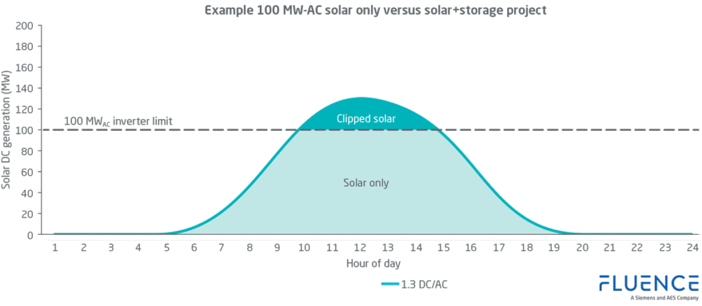
Figure 2: Clipping occurs when the energy delivered by the PV panels exceeds the capacity of the P.V. inverter. (Image: Fluence)
A single inverter in DC-coupled PV+BESS installations can be a drawback and result in less operational flexibility. In an AC-coupled PV+BESS, if the BoP is sized large enough, the system can simultaneously deliver power to the grid from the PV array and the BESS. That’s impossible with a DC-coupled system where the single inverter limits the maximum power delivered to the grid.
Increased sustainability on the edge
Using a DC-coupled PV+BESS architecture can increase energy production at the edges of the PV system operation. Inverters are designed to begin operation once a minimum threshold voltage is reached. For an inverter designed for a grid-scale PV installation with a 1.5 kVdc nominal bus voltage, the so-called “start-up” voltage is about 500 Vdc. During morning and evening hours when the sun is low on the horizon or during periods of significant cloud coverage, the PV array voltage can dip below the 500 Vdc thresholds, and any energy generated can be lost. The dc-dc converter and BESS increase energy capture and sustainability on the edges of solar insolation by storing energy when the bus voltage is below the start-up voltage of the inverter (Figure 3).
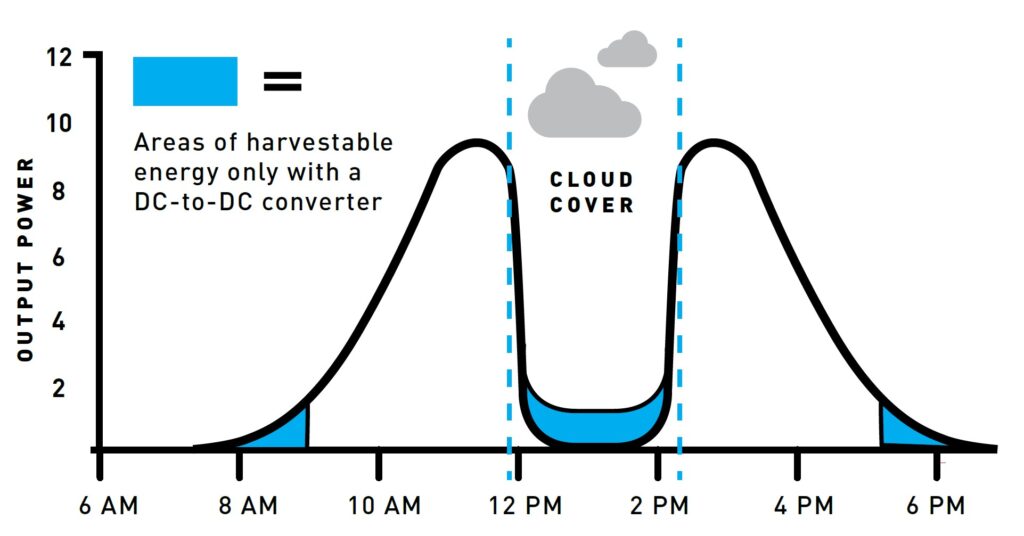
Figure 3: A DC/DC converter can capture energy that would otherwise be lost on the edges of P.V. harvesting when the bus voltage is below the start-up voltage of the inverter. (Image: Dynapower)
Voltage mapping for increased energy production
One of the challenges when implementing a DC-coupled PV+BESS installation is the difference between the battery system voltage and the PV power bus voltage. Batteries require a specific voltage profile for reliable operation. That voltage is often related to the battery’s state of charge (SoC). The bus voltage for maximum PV power generation depends on the type of panels being used and operating conditions like temperature and insolation. A typical 1.5 kV P.V. array can generate maximum power point voltages from 900 to 1,300 Vdc. A typical utility-scale BESS can have an SoC range from 600 to 900 Vdc for Li-ion batteries and up to 1,250 Vdc for vanadium flow batteries.
The PV bus and battery SoC voltages vary independently from each other, increasing the complexity of maximizing overall system efficiency. The dissimilar voltage ranges of the BESS and the P.V. elements can be easily handled with the bidirectional inverter in an AC-coupled architecture. But the use of an AC-coupled architecture can suffer from energy clipping and lower energy production on the edges of insolation, as discussed above. Instead, a DC-coupled architecture with a galvanically isolated bidirectional dc-dc converter with integrated voltage mapping can be used to manage the different voltage profiles of the PV array and BESS. DC/DC converters with integrated voltage mapping are sometimes called dc-dc optimizers.
The control circuitry in dc-dc optimizers enables the different voltage ranges of the PV and BESS sections to be automatically mapped into each other. Voltage mapping can be performed using static or dynamic techniques or both in the same optimizer (Figure 4):
- Static voltage mapping equalizes the difference between the means of the PV MPPT range and the BESS SoC range.
- Dynamic voltage mapping equalizes the PV and BESS voltages within their respective ranges during system operation under various energy demands and weather conditions.
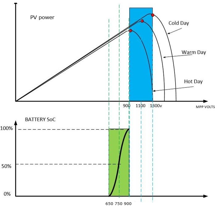
Figure 4: Voltage mapping is used to reconcile the different operating voltage ranges of the P.V. and BESS sections. (Image: Alencon)
Summary
DC coupling can bring performance benefits to PV+BESS installations; but it’s not that simple, and it’s not a panacea. In some instances, using a DC-coupled system can reduce operational flexibility. And while using a DC-coupled system can help capture more PV energy on the edges of sufficient insolation and prevent energy clipping during periods of high insolation, there is increased control complexity related to implementing dc-dc optimizers for the static and dynamic voltage mapping needed to match the voltage profiles of the P.V. array and the BESS.
References
A battery for hire: A.C. vs. D.C. coupling for solar + energy storage projects, Fluence
A.C. v. D.C. Coupling For Solar Plus Energy Storage Projects, Dynapower
Energy storage systems that maximize P.V. production and profits, Dynapower
Evaluating the Technical and Economic Performance of P.V. Plus Storage Power Plants, National Renewable Energy Laboratory
How to optimize your inverter loading ratio for solar + energy storage projects, Fluence
Voltage Mapping: The Key to Making DC-Coupled Solar + Storage Work, Alencon



Tell Us What You Think!